How I Designed a 3D-Printed Laminar Flow Nozzle
- 3d-printing
- fluid-dynamics
- laminar-flow
- prototyping
- gardening
There is something mildly unreasonable about connecting an ordinary garden hose to a printed part and expecting the water to leave as a clear, smooth rod.
Mk2.2 3D-printed laminar-flow nozzle producing a smooth water stream outdoors.
1 / 2That was the attraction. A hose normally gives you a lively, turbulent stream. I wanted to see how much of that turbulence could be negotiated away with geometry that came directly off an FDM printer.
The result became three generations of garden-hose laminar-flow nozzles. Mk1 proved that the idea could work, but relied on packed diffuser material and leaked more than I wanted. Mk2 moved much more of the flow conditioning into the print. Mk3 separated the mechanism into swappable stages so I could test the diffuser, straightener, exit chamber, and outlet lens independently.
Two key lightbulb moments
Two ideas eventually changed how I approached every later revision: work with the texture produced by the printer, and pay close attention to pressure stability. A key to maintaining laminar flow is stable, evenly distributed pressure; using more straws creates additional surface area that helps dampen disturbances and keep the flow consistent.
Print with the flow
FDM passage walls are not perfectly smooth. When water crosses the rounded edges of successive printed layers, each ridge is another opportunity to disturb the flow near the wall. Orienting the straightener so its dominant layer texture runs downstream reduces those cross-stream interruptions. It does not remove surface roughness; it turns that roughness in the less disruptive direction.
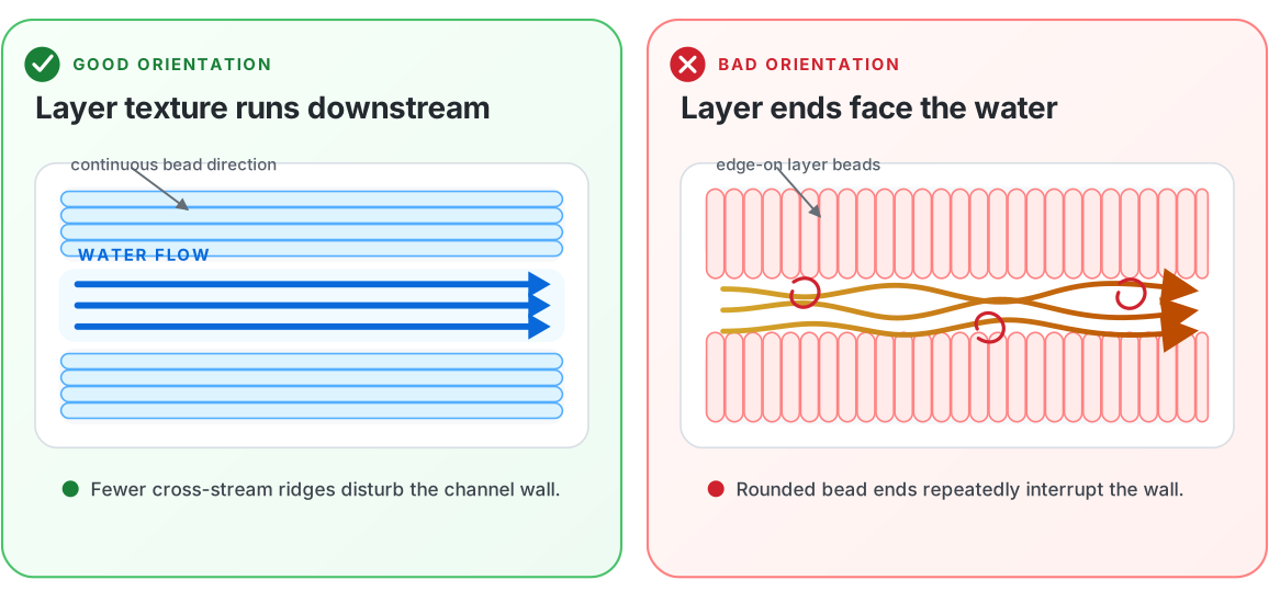
A squeezed hexagonal lattice made that orientation practical. It creates many long, narrow, self-supporting passages as repeatable printed geometry, replacing the bundle of drinking straws traditionally used as a flow straightener.
Normalize pressure instead of adding length
The early Mk2 body treated extra length as extra settling space. In practice, an elongated body could preserve an uneven axial pressure path all the way to the outlet. From Mk2.2 onward, the design became deliberately “fat”: a shorter, wider chamber gives the flow a broader region in which to equalize pressure before it reaches the lens.
- Entry chamber — The hose enters at 90 degrees instead of pointing directly at the outlet. The chamber gives the incoming water room to settle before it reaches the conditioning stages.
- Diffuser — A printed cross-hatch interrupts and dampens the larger turbulent structures created by the hose, fitting, and sharp inlet transition.
- Straightener — Many narrow, parallel passages encourage the water to move in the outlet direction. This part is printed on its side so the layer lines run parallel to the flow.
- Exit chamber — A short, wide volume lets the conditioned streams meet again while encouraging more uniform pressure across the outlet.
- Lens — The interchangeable nozzle insert controls the final diameter, edge quality, and shape of the water column.
In theory the strategy is to calm the incoming water, divide it into smaller channels, give those channels enough length to straighten, bring them back together without reintroducing a large pressure difference, and then pass the combined flow through a clean lens outlet.
That last part matters more than it first appears. A polished, accurately printed lens can preserve the conditioned flow. A rough edge, damaged opening, or badly sealed insert can undo much of the work performed upstream.
This article is the design and printing guide behind those models. If you only want the files, the 3D Printable - Laminar Flow project page collects all three versions in one place.

3D Printable – Laminar Flow
My three-version 3D-printable garden hose laminar-flow nozzle project, moving from packed diffuser material to a stator-style core.
Mk1 used packed diffuser material, Mk2 moved more flow conditioning into the print, and Mk3 uses cleaner internal channels with a stator-style core.
Behold: the Mk3
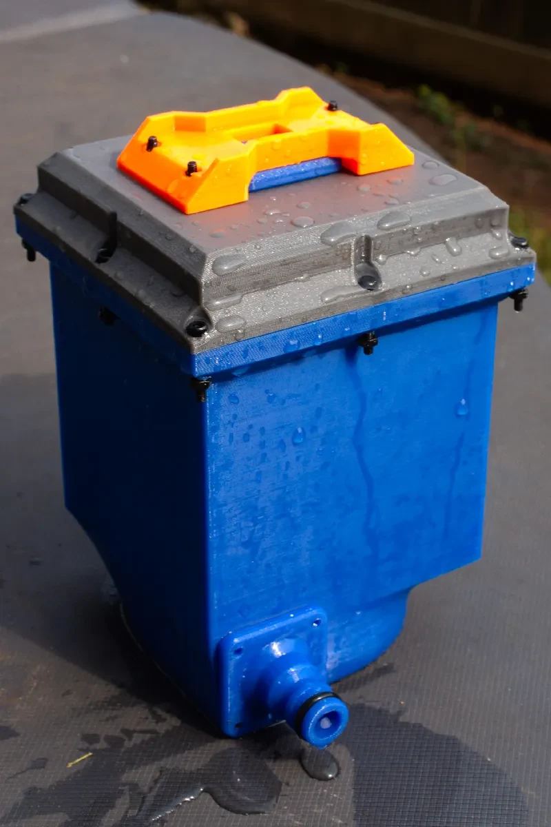
The best versions produce the familiar glass-rod effect: a stream that looks almost motionless until it breaks up farther from the outlet.
What is laminar flow?
Laminar flow describes fluid moving in orderly layers rather than mixing through chaotic eddies.
Splitting one large, fast stream into many smaller passages reduces the characteristic diameter and makes orderly flow easier to support. The visual test is then whether the streams can recombine and leave the lens with a stable profile.
So when I call this a laminar-flow nozzle, I am describing both the internal design goal and the stable glass-rod stream it produces.
Mk1: proving a printable hose nozzle could work
Mk1 was the useful kind of first prototype: good enough to prove the idea and awkward enough to make the next version obvious. It used a small piece of steel wool or Brillo-style material between the hose attachment and the middle section. That packed material acted as a diffuser and helped equalize pressure before the water entered the straightening channels.
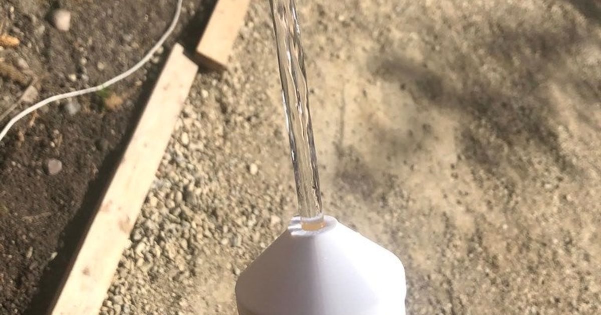
The output could become impressively smooth at gentle flow rates, but the nozzle had several limitations:
- The body and joints could leak.
- The stream was not always uniform across the outlet.
- Loose diffuser material made assembly and repetition less predictable.
- More of the final result depended on finding and packing non-printed material correctly.
The model includes STEP files, so it still has value as a starting point for remixes. For my own progression, its main contribution was proving that a garden-hose attachment could produce a stable enough stream to justify another round of design.
Mk2: moving the work into the print
Five years later, Mk2 revisited the same problem with more modelling and printing experience. The central question changed from “Can this work?” to “How much of the mechanism can the printer create for me?”
Mk2 uses a print-in-place body with a settling region, printed diffuser geometry, a straightener, and interchangeable outlet lenses. The straightener applies the first epiphany with a squeezed hexagonal lattice in place of a bundle of loose tubes. The hexagons self-support at printable angles, and the channels provide a length-to-diameter ratio greater than 40:1.
Printing the body sideways makes that geometry practical. It avoids a tall, narrow print and aligns the straightener's dominant layer texture with the water instead of presenting each bead edge across the channel. The included 6 mm, 7 mm, and 8 mm lenses make the outlet easy to change without redesigning the complete body.
Mk2 also exposed the pressure problem. Its early body was long and narrow, the water entered along the same axis as the outlet, and the narrowing exit could preserve an uneven pressure profile through the middle of the nozzle. Those observations led directly to the shorter, wider Mk2.2 and became part of the design brief for Mk3.
Why Mk2.2 may be the best first print
The later Mk2.2 “fat” revision applies the pressure-normalization epiphany in a smaller, simpler body:
- A shorter, wider form encourages more uniform pressure.
- The hexagonal body reduces difficult overhangs.
- The diffuser is included in the print.
- No screws are required.
- The footprint remains smaller than Mk3.
- Initial testing produced a much cleaner stream than the earlier Mk2 revisions.
If your goal is to print a working garden-hose laminar-flow nozzle rather than to experiment with every internal stage, Mk2.2 is the version I would start with.
Mk3: making every stage testable
Mk3 trades some simplicity for control. The body uses a clamshell arrangement so the diffuser and straightener can be printed in deliberate orientations, removed, replaced, and compared. Water enters from the side, passes through the diffuser and straightener, expands into a wider exit chamber, and leaves through a push-fit lens.
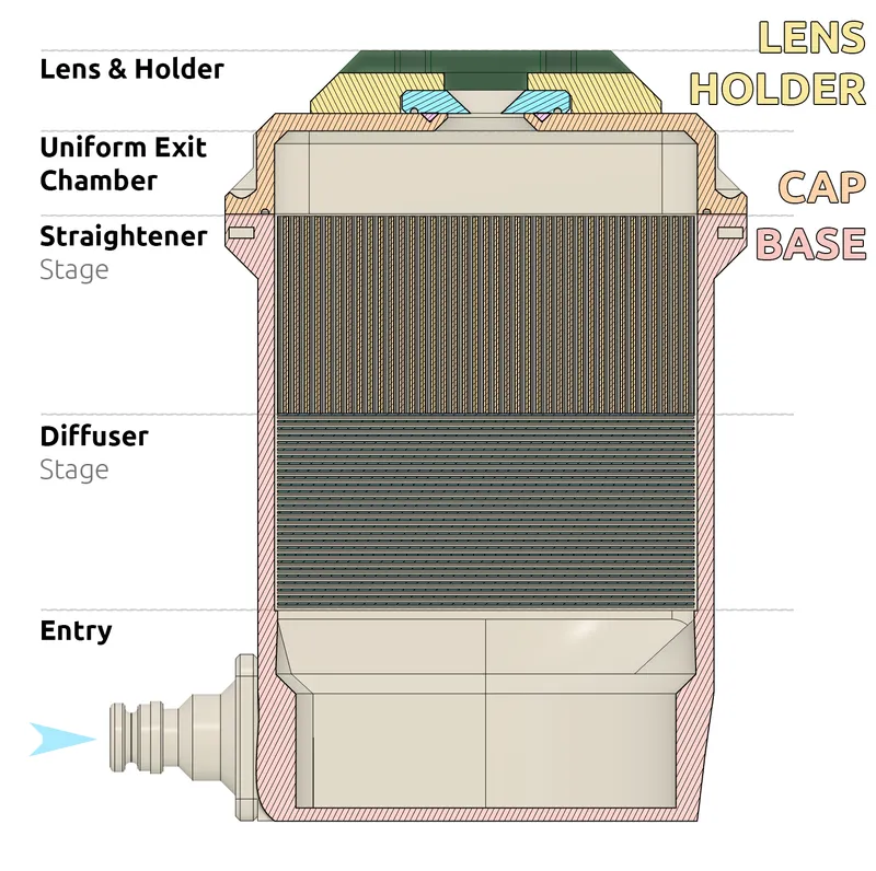
The discrete stages make Mk3 a better platform for experiments:
- Diffuser patterns can be changed without reprinting the complete body.
- Straightener channels can be printed with continuous layer lines parallel to the water.
- Lenses can be swapped while the hose is still running.
- Different lens diameters, materials, surface finishes, and shapes can be compared quickly.
- The larger exit chamber makes it easier to pursue uniform pressure before the outlet.
The tradeoff is a larger print and more assembly. The current design uses a printed base and cap, separate diffuser and straightener parts, a lens holder, a TPU lens gasket, and M3 hardware. Mk3 is the version I prefer for understanding and modifying the mechanism; Mk2.2 is the more accessible recommendation when you mainly want the finished stream.
Which version should you print?
Mk1: the original experiment
Print Mk1 if you want a simpler model to remix or the history of how the series began. Expect loose diffuser material and more attention to sealing.
Mk2.2: the approachable first print
Print Mk2.2 if you want a smaller footprint, no screws, printed flow-conditioning geometry, and a strong visual result.
Mk3: the modular test platform
Print Mk3 if you want independently printable stages, swappable internal geometry, and hot-swappable outlet lenses.
All three models are available from the laminar-flow project hub, along with the image galleries and direct Printables downloads.
Printing notes
The supplied Mk2 and Mk3 print files were developed around a 0.4 mm nozzle and 0.25 mm layers. PETG is my default recommendation for an outdoor hose attachment, and it is the material used for the prototypes described on Printables.
Several details matter more than chasing an unusually small layer height:
- Verify that the thin walls in the hexagonal or straightener pattern actually appear in the slicer. With a different nozzle width, some channels may disappear completely.
- Print the straightener in the supplied orientation. On Mk3, the part is placed so its layer lines run parallel to the direction of the water.
- Increase bridging speed if the slicer predicts an extremely long Mk2 print. The early settling region uses many bridges, and minor cosmetic artifacts there are less important than preserving the internal structure.
- Use enough perimeters and infill to make the hose connection mechanically strong and water resistant.
- Inspect and clean the outlet lens carefully. A small string, burr, or damaged edge can disturb the stream.
- Test for leaks at low pressure before opening the hose farther.
Mk2 needs a 3/8-inch O-ring at the Gardena-style connector. Mk3 uses a TPU gasket around the lens system and M3 hardware to join the clamshell and lens holder. A thin application of silicone sealant around the lens interface can help if water escapes around the insert instead of through it.
Troubleshooting an uneven stream
If the stream breaks up immediately, start at the outlet. Check the lens for a rough inner edge, debris, print strings, distortion, or an uneven seal.
If the center of the stream behaves differently from the edges, reduce the flow rate and look for a pressure imbalance. A direct axial inlet, small exit chamber, blocked straightener channels, or uneven diffuser can preserve a higher-pressure path through the middle.
If the nozzle only behaves at very low flow, the straightener passages may be too large or too short for the supplied flow rate. Reducing the lens diameter may make the visual result worse by increasing velocity, even though the smaller opening looks cleaner on the workbench.
Up Next: Can we FDM print a laminar-flow hood? 🤔
A laminar-flow hood applies similar flow-conditioning ideas to air instead of water: diffuse an uneven incoming flow, equalize pressure, and produce a smooth, uniform stream. Could an FDM-printed plenum, filter housing, and airflow straightener work with a suitably sized blower and HEPA filter? The real challenge would be controlling leaks and turbulence, maintaining even pressure across the filter, and verifying airflow and particle performance.
Related printed water projects
The Modular Hydroponic Tower Garden and Infinity Bowl approach water from different directions, but they share the same practical lesson: printed geometry is only part of the system. Fittings, seals, pressure, maintenance, print orientation, and revision history matter just as much as the shape on screen.
The complete laminar-flow series is available here:
For the consolidated project history, galleries, and links, visit 3D Printable - Laminar Flow.